

Creating a simple and cheap fan controller
From the need to the idea to the solution
After upgrading my computer with the new Ryzen 5800x series, the new motherboard did not include a header to connect my water temperature sensor. This lead the control of my fans to be limited to the temperature sensor inside the processor. This would be okay if I used regular processor cooling, which has a small thermal mass and has good thermal conductivity. However, in my case, I have a water cooling where the temperature of the radiator depends on the water temperature and not so much on the current processor temperature. There is a huge delay in the order of minutes before the water heats up due to the large thermal mass it presents. Therefore the control that acts on the same timescale as workload increases (seconds) is an ill fit. Therefore I used the water temperature, which was read out on the previous motherboard. Unfortunately, the motherboard that I got on sale did not have this. Fortunately, fans can easily be controlled by PWM hence this article will guide you to create a very simple and cheap PWM fan controller. But first what is PWM?
Pulse-Width Modulation (PWM) for fans
To control the fans the motherboard sends out signals that determine the speed fans should run at. The main reason to reduce the fan speed is to reduce the noise it makes. The lower speed is okay as, under a low processor load, the amount of heat that should be dissipated is low. PWM is a signal and a way of communication that tells the fan at what speed it should run. It is a digital signal and has a high (on) and low (off) level as shown here.
The frequency (f) of the PWM signal depends on the total time ($T_{on}+T_{off}$), \(f = \frac{1}{T_{on}+T_{off}}.\) The speed of the fan in percentage depends directly on the duty cycle (DT) in percentage, \(\mathrm{DT}=\frac{T_{on}}{T_{on}+T_{off}}.\) so if DT is 0.6 or 60% the speed of the fan will be 60% of its maximum speed.
The temperature of a thermistor
Okay, we know how to create the signal but how do we know what speed the fans should run at. Depending on the amount of noise you allow at a certain water temperature, the water temperature is key. To find this out we need to translate the resistance of a thermistor back to a temperature. Typically these have a negative temperature coefficient, meaning the resistance decreases as the temperature increases. Since I do not know the model or make of my thermistor, I hoped a commonly used model would be a good fit. The temperature ($T$) as function of the resistance ($R_T$) according to the Steinhart-Hart equation. \(\frac{1}{T}=C_1+C_2\ln{R_T}+C_3(\ln{R_T})^3\) The other option was the $\beta-$equation which is an exponential relationship and can be extended to the Steinhart-Hart equation.
Requirements for the PWM fan controller
- The PWM frequency of computer fans is typically 25 kHz but please check the datasheet.
- Read temperature from a thermistor
- The speed range for my fans was 30-100%
Tackling each problem 1-by-1
I separated the core functionalities of the fan controller into 3 parts.
1) Microprocessor choice and coding a PWM signal
At the beginning of this year, I programmed a variable duty cycle on an Arduino nano. Achieving a PWM frequency of 1 MHz is not possible with the built-in PWM functionality and neither is it variable at the resolution that I wanted (8-bit). To do this I went down one level and set the registers of the timers. However, my experience learnt me this took quite some development time. Therefore, this time I opted to use a different microcontroller where I could just use higher-level functions and generate the PWM signal according to my needs as simple as a few lines of code. I found an STM32F103C8T6 (STM32 black pill) lying around in my closet and found this library that had everything I needed.
2) Temperature readout by voltage divider
Just like in one of my past articles I used a voltage divider to find the thermistor resistance. Putting $R_T$ at the position of $R_2$, it can be found from the output voltage as, \(R_T = \frac{R_1}{V_{out}}\) With $R_1$ a chosen resistance in my case 4.7 k$\Omega$. Since the thermistor model is a linearization that is accurate in a certain range, I chose $R_1$ such that it is similar to $R_T$ during computer idle.
To find the coefficients, you would take measurements of $R_T$ at for example three different temperatures. Since my sensor was already mounted in the system and it doesn’t have to be very accurate I took a random measurement found on the internet for the same kind of thermistor that I had which is a 10 k$\Omega$-thermistor. Plugged 3-points into this tool for 25, 50, and 70 $^\circ$ C, which is the range I expect the water to be in and thus the sensor to be exposed to.
3) Defining different speed ramp up ranged depending on temperature
To create a silent system, you want initially the fan speed to be low at low temperatures and high at high temperatures. But what is low and what is high? Since my fans can not be run below 30%, this was the lower limit (this is not exactly true but I will discuss this later). For heat transfer to occur via convection, there needs to be a temperature difference between the radiator (I assume it is equal to the water temperature) and the environment. My room is typically below 30$^\circ$C therefore up to let say a water temperature of 40$^\circ$C the fans run in the lowest setting and then they should gradually increase. This is split into 2 different ramps in my code which reduces the fan noise. Whenever a lot of heat is dumped into the water, the fans will still go to 100%. This point was chosen to be 70$^\circ$C, because the tubes start to melt at 74$^\circ$C according to the manufacturer. **Be careful that water will slowly evaporate even below its boiling point of 100 $^\circ$C. **
Extra) true 0% PWM
Sometimes you might want to go lower than 30% or even turn it off to save power but also to prevent noise. I did not do this as this extra step, requires a lot of effort for very little gain in my case. However, should you want this. The fans can be turned off by setting the PWM duty-cycle to 0%, however most fans don’t support this. In the case when water temperature is already below what you like, in my code 40$^\circ$C. You could switch off a MOSFET thus set the gate voltage to low or 0 V and when it s above 40$^\circ$C you would turn it on. The MOSFET should then connect between your black wire (anode) from your fan and the anode of your power supply. In the situation the fans should be off, the electronic circuit is broken by the switch and no current will be able to flow.
Connections
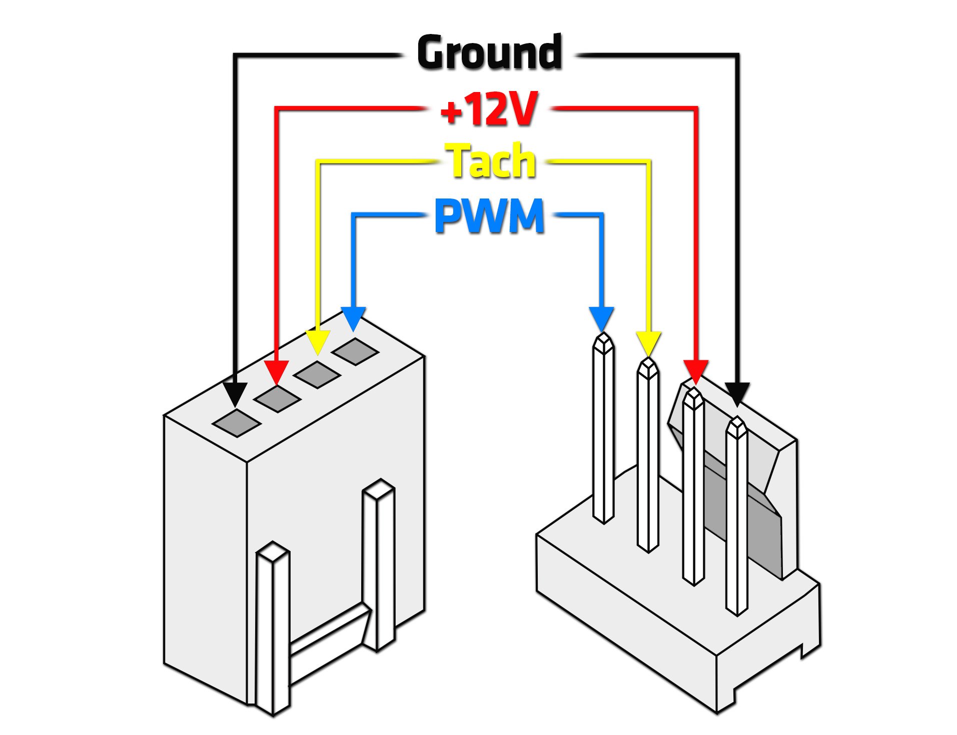
Since the connection diagram is quite simple I do it in words. The thermistor has 2 pins (there is no polarity) and should be connected as in the voltage divider, 1 to ground and 1 to $R_1$. Finally, the PWM signal is output at pin PA8 and this should go to the PWM pin as follows,
Lastly, power for the microcontroller can be supplied over the micro-USB.
The final code
#include <Arduino.h>
#define inLED PB12
#define PWMpin PA8
#define SERIAL_PORT Serial1
#define f_PWM 25000
#define PWMstatic 30
#define SAMPLES 100

HardwareSerial Serial1(PA_10, PA_9);
//Thermistor const
#define T_waterpin PA7
int Vo;
float Rchosen = 4582;
float logR2, R2, T;
float c1 = 1.133027435e-03, c2 = 2.334426745e-04, c3 = 0.9074747924e-07;

//code variables
float Ttest;
int PWMdynamic = 0, PWMold= 0;
int  i, Vs;
bool paused = 0;

//init specifics of the hardware timer and which effectively pin
TIM_TypeDef *Instance = (TIM_TypeDef *)pinmap_peripheral(digitalPinToPinName(PWMpin), PinMap_PWM);
uint32_t channel = STM_PIN_CHANNEL(pinmap_function(digitalPinToPinName(PWMpin), PinMap_PWM));
//Timer object init with previous intel
HardwareTimer *MyTim = new HardwareTimer(Instance);   // no need to configure pin, it will be done by HardwareTimer configuration

float reading_to_temp(int number, int R1){
  int temp;
  R2 = R1 / (1023.0 / (float)number - 1.0);
  logR2 = log(R2);
  temp = (1.0 / (c1 + c2*logR2 + c3*logR2*logR2*logR2));
  temp = temp - 273.15;
  return temp;
}

void setup() {
  pinMode(inLED, OUTPUT);
  digitalWrite(inLED, LOW);
  MyTim->setPWM(channel, PWMpin, f_PWM, PWMstatic);            // 5 Hertz, 10% dutycycle
}

void loop() {
  //improve averaging of analogread by oversampling because required speed is only ~ Hz.
  Vs = 0;
  for(i = 0; i < SAMPLES; i++){
    Vs = Vs + analogRead(T_waterpin);
  }
  Vo = Vs / SAMPLES;
  T = reading_to_temp(Vo, Rchosen);
  Ttest = T;
  if(Ttest <=40){
    PWMdynamic = 30;
    //MyTim->pause();
    paused = 1;
  }
  else if(paused){
    paused = 0;
    //MyTim->resume();
  }
  if(Ttest > 40 && Ttest <= 60){
    PWMdynamic = 30 + 25 * (Ttest - 40) / 20;
  }
  else if(Ttest > 60 && Ttest <= 70){
    PWMdynamic = 55 + 45 * (Ttest - 60) / 10;
  }
  else if(Ttest > 70){
    PWMdynamic = 100;
  }
  //hysteresis to keep number of updates small and prevent oscillatory behaviour.
  if( abs(PWMdynamic - PWMold) > 3){
    MyTim->setCaptureCompare(channel, PWMdynamic, PERCENT_COMPARE_FORMAT);
    PWMold = PWMdynamic;
  }
}
Final cost
| Component | Cost ($\euro$) |
|---|---|
| Resistor 4k7 | 0.01/free |
| Black pill (STM32F1) | 3.63 |
Any other STM32 series MCU would work as long as it is supported by the library. It seems my version of black pill is end of life, the new version would work also. Please be careful for the pin assignment, which could be different.
Comments