
RGB lights even on your stairs
RGB on stairs that is boring
Is what you might think. But let’s spice it up a bit by making them user aware. Okay, let’s put a motion sensor nearby and this activated the lights when you are in the vicinity. Well… no it can be even cooler, how about making it stair-step-aware?!
stair-step-awareness
Wouldn’t it be cool if the stairs would light up exactly on your current step? I think it would be and that is exactly the goal of today. Towards this, I designed a custom system that adds some flair to your stairs! It consists of three main components,
- Addressable RGB led-strip
- Step presence detection
- Controller
Addressable RGB led-strip
To look cool I didn’t opt for just a white led-strip but an RGB one that is individually addressable, because we want to do cool things with it… Such as stair-step awareness (SSA). Our stairs have 12 steps each of approximate length of 1 meter. This means I need 12 meters of LED strip, luckily due to mass fabrication these can be and are quite cheap, but what should one choose? It depends on a few factors but I mainly concentrated on,
Voltage drop on an RGB led-strip and my choice
The main factor to consider here is that at 12 meters in length the voltage drop can be quite significant, hence choosing LED chips that work with a higher operation voltage are more convenient to use. Why is this? Consider for similar LED efficiency (the same amount of energy is required to give a certain amount of light), the power is constant then for LED with higher operation voltage less current is required. Then by Ohm’s law \(V_{drop} = I^2R\) is lower for LEDs with higher operating voltage. This means the LED strip will not become dim over its length. Additionally, one could opt to connect the power source at regular intervals on the total LED strip, however this requires additional wire and floor planning. Therefore, it is better to choose a more suitable LED strip. The most common options are, 5 V and 12 V. Since 5 V is the lowest option here, 12 V is preferred because of the lower voltage drop. This made my choice to fall on the WS2811 the higher voltage brother of the WS2812B which is common in many projects.
Brightness, trueness of color and power consumption, etc.
In the end there are many more factors to consider. Some LED strips are better in some of the factors but in the end the WS2811 was the cheapest per meter and suited my needs. Some alternatives are, SK6812 and APA102.
Step presence detection
To achieve the SSA, we need to somehow know when someone is on a step. Let’s consider some mechanics and imagine you are standing on a stair-step. When you step on a step, your foot is on the step. This induces pressure but also your foot is physically there. I came up with the two following mechanisms to detect the presence on a certain step.
- Light-blocking
- Pressure
Light-blocking
When your foot is on the step it is physically there. This means if there is a light sensor it would be blocked off by your foot. This could be sideways or in the step itself as depicted here. 
These methods have a few cons, for sideways you would require an additional light source. For in you can use your natural lighting such as diffuse light, however, this would not work very well at night. Also, the intensity can vary over the day so you would need some automatic calibration to distinguish between low light or ‘is being stepped on’ conditions.
Pressure
Since the light-blocking method is possible. I deemed it too complex to do, so I thought of an alternative. Where I use pressure sensors and with this in my I went ahead and found two types of pressure sensors
- Strain-gauge
- Thin-film pressure sensor
The strain gauge required me to glue them on the backside of the stairs. In that way, it can bend together with the wood and hence measure presence. This required a lot of glue and modifications so I did not prefer this.
Whereas thin films can be placed very unobtrusively onto the stair-step. Since we were planning to use stair nosings profiles, they could be perfectly hidden underneath them. These sensors have huge resistance and once it compresses the resistance decreases. So the controller needs to read the resistance in some smart way to detect presence. More on that below…
Controller
In this project I needed two main functionalities to be achieved by this controller.
1) The controller knows which step I am standing on, SSA 2) Correct color is sent to the RGB led-strip
One of the most known microcontrollers is the Arduino since it is so popular a lot of libraries are created for it and this makes my life a lot easier. Less time spent on re-inventing the wheel is more time to do cool projects. But, not only software is needed but also hardware since we are using real physical sensors.
Thin-film pressure sensor readout
The circuitry that is used is very simple, there are two states. Either you are on the step or you are not on the step. These two states can be distinguished by looking at the resistance of the sensor, this means we need to distinguish between high and low resistance states. As mentioned before the resistance decreases if it is compressed hence it makes sense to choose everything below a certain threshold, that is the on the step state and everything above is not on the step state.
Comparator to sense the state
To achieve state readout we can use a comparator, which can be explained with the following image,
It basically does what I explained before, if you use a 5 V supply it makes sense to set \(V_{REF} = 2.5V\) and thus choose the resistors equally. However, since I have 12 steps I have to do this 12x?
Time multiplexing is less hardware
Since OPAMPs are not very cheap ~ €1,- a piece and the number of control pins on the Arduino is limited I chose to do time multiplexing. In time-multiplexing I make use of the fact that I don’t need to constantly know whether someone is on the step, but only once in a while. The Arduino’s clock frequency is 32 MHz so I could read out my stairs at MHz speeds which means million times per second. But I don’t need to know it that often hence I could easily divide this by 12 and read all 12 steps with time multiplexing.
Electronics schema for LED controller PCB
To achieve all of the hardware functionalities I created a small PCB that neatly packs everything together, with its schema below
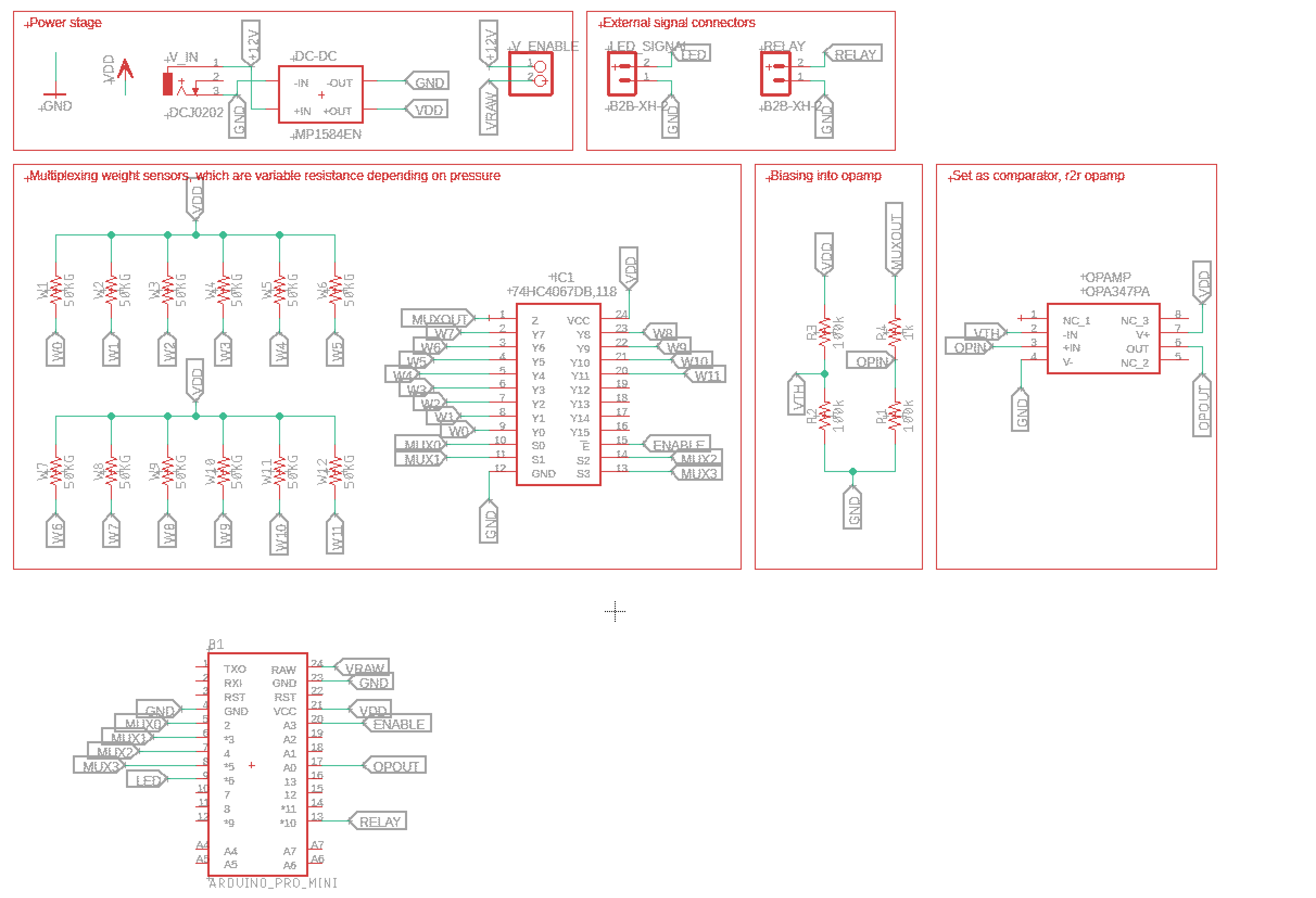
A few things to note from left to right and up to down.
- I used a DC-DC converter so I could use a single supply for LED and my controller PCB.
- Some external connector to connect to the LED strip and also control a relay if needed
- Time multiplexing where W0-W11 are the pressure sensors and IC1 is the multiplexing chip
- Biasing for the comparator circuit achieved with OPAMP
- R4 series resistor to prevent short circuits of the weight sensor
- R1 is a pulldown resistor
- The Arduino, pro mini because it is cheap
---
**NOTE**
The labels with same name means they are connected together
---
Arduino code for controller
To make everything work together of course code is needed. So the software has these functionalities, when the presence is detected it turns all the lights on to CRGB on(122,122,122). The step above your current step will be set to CRGB stepColordown(255,0,0) and the step below your current step will be CRGB stepColorup(0,255,0). After it turns on and the presence is gone, it will fade to CRGB bgColor( 122, 122, 122) and after 15 seconds it will fade to no light CRGB off(0,0,0).
The main things to change to your needs is in the first few lines,
#include <Arduino.h>
#include "FastLED.h"
#include "Mux.h"

using namespace admux;

// Hardware settings CHANGE THIS
#define NUM_LEDS 16 //number leds per step (16)
#define NUM_STEPS 12 //number of steps
#define STOP_TIME 15000 //after this time turn it off

//init mux object
Mux mux(admux::Pin(A0, INPUT, PinType::Analog), Pinset(2,3,4,5)); // need admux:: because pin doubly defined

#define detectPin 14 // pin connected to output of comparator/OPAMP
#define enPin 17 //pin for relay
#define DATA_PIN 9 //pin that is connected to led strip

#define TOT_LEDS NUM_LEDS*NUM_STEPS

//time keepers
unsigned long start=0, stop=0;
CRGB leds[TOT_LEDS];
//set your colors
CRGB stepColordown(255,0,0);
CRGB stepColorup(0,255,0);
CRGB bgColor( 122, 122, 122); //white
CRGB off(0,0,0);
CRGB on(122,122,122);
// NO CHANGES NEEDED BELOW except color order in setup()
int detected=0;
int channelDetected = 0;

// Helper function that blends one uint8_t toward another by a given amount
void nblendU8TowardU8( uint8_t& cur, const uint8_t target, uint8_t amount)
{
  if( cur == target) return;

  if( cur < target ) {
    uint8_t delta = target - cur;
    delta = scale8_video( delta, amount);
    cur += delta;
  } else {
    uint8_t delta = cur - target;
    delta = scale8_video( delta, amount);
    cur -= delta;
  }
}

// Blend one CRGB color toward another CRGB color by a given amount.
// Blending is linear, and done in the RGB color space.
// This function modifies 'cur' in place.
CRGB fadeLedtoColor( CRGB& cur, const CRGB& target, uint8_t amount)
{
  nblendU8TowardU8( cur.red,   target.red,   amount);
  nblendU8TowardU8( cur.green, target.green, amount);
  nblendU8TowardU8( cur.blue,  target.blue,  amount);
  return cur;
}
// Fade an entire array of CRGBs toward a given background color by a given amount
// This function modifies the pixel array in place.
void fadeSteptoColor(uint16_t step, CRGB* L, uint16_t N, const CRGB& bgColor, uint8_t fadeAmount){
    for(unsigned int j = 0; j < N; j++){ // N is number of leds per step to fade
    fadeLedtoColor(L[step*N+j], bgColor, fadeAmount);
  }
}

void fadeAllstepsTocolor(CRGB* L, uint16_t N, const CRGB& bgColor, uint8_t fadeAmount, uint16_t noofsteps){
  for( uint16_t i = 0; i < noofsteps; i++){
    fadeSteptoColor(i, L, N, bgColor, fadeAmount);
  }
}

int readChannel(int chnl){
  int16_t data;

  mux.channel(chnl);
  delay(5); //don't need full speed let it settle
  data = mux.read();
  Serial.print("Potentiometer at channel "); Serial.print(chnl); Serial.print(" is at "); Serial.print((double) (data) * 100 / 1023); Serial.println("%%");
  if(data > 511) return chnl + 1;
  else return 0;
}

void changeSteplight(int step, CRGB& color){
  for(int j = 0; j < NUM_LEDS; j++){
    leds[step*NUM_LEDS+j] = color;
  }
}

void setAllotherSteps(int mystep, CRGB myColor){
  int i = mystep;
  for(unsigned int j = 1; i+j<NUM_STEPS; j++){
    changeSteplight(i+j, myColor);
  }
  for(unsigned int j = 1; i-j+1>0; j++){
    changeSteplight(i-j,myColor);
  }
}

void setAllsteps(int mystep, CRGB myColor){
  for (int i = 0; i < NUM_STEPS; i++){
    changeSteplight(i, myColor);
  }
}

void setup() {
  pinMode(enPin, OUTPUT);
  pinMode(detectPin, INPUT);
  pinMode(LED_BUILTIN, OUTPUT);
  digitalWrite(LED_BUILTIN, LOW);
  digitalWrite(enPin, LOW);
  FastLED.addLeds<WS2811, DATA_PIN, BRG>(leds, TOT_LEDS); //set your color order for me BRG
}

void loop() {

  for (int i = 0; i < NUM_STEPS; i++){
    channelDetected = readChannel(i);
    if(channelDetected){
      digitalWrite(LED_BUILTIN, HIGH); //T
      detected++;
      start = millis();
      setAllsteps(i, bgColor);
      changeSteplight(i,stepColordown);
      if(channelDetected > 2) changeSteplight(i-2,stepColorup); //note that if channeldetected = 1, i = 0
    }
  }
  if(detected){
    fadeAllstepsTocolor(leds, NUM_LEDS, bgColor, 1, 5);
  }
  if(millis() - start > STOP_TIME){ // keep lights on for set time
    detected = 0;
    //FastLED.clear(); // hard turn off
    fadeAllstepsTocolor(leds, NUM_LEDS, off, 1, NUM_STEPS); //soft turn off
  }
  FastLED.show();
}
Final words
Well enjoy that all :)
Learnings and references
- Consider not only the number stair-step but also one more which is even to the floor.
- It is a pain to make so many long connectors, 12 sensors…
Comments